記事中のプログラムは,Arduino IDE 2.1.1, Board Manager esp32 ver. 2.0.9 で動作確認しています.
信号処理をするにはDSPライブラリがあると大変便利である.ESP32ではどうなっているのか調べると,Espressif DSP Library があり一通りメジャーな処理は用意されている.ただ,Arduino IDE で使えるかどうかが問題.
ESP32のボードマネージャがインストールされたフォルダを調べてみると,かなり深い階層の非常に見つけ難いところに,ヘッダファイル(esp_dsp.h)が置かれていた.どうやらソースコードはないがライブラリも入っている様子.
試しに,IIRフィルタ(2次LPF)を実装してみた.
コードを下に示す.前回からに変更部分はハイライト表示してある.
// I2S on ESP32-S3
// T.Uebo  October 1 , 2022

// I2S Master MODE 48kHz/32bit
//
//   Mclk  GPIO 0
//   Bclk  GPIO 42
//   LRclk GPIO 2
//   Dout  GPIO 41
//   Din   GPIO 1

#include <esp_dsp.h>
#include <driver/i2s.h>
#define fsample 48000
#define BLOCK_SAMPLES 64
#define MUTE 40 // MUTE control (LOW: Mute)


//buffers
int rxbuf[BLOCK_SAMPLES*2], txbuf[BLOCK_SAMPLES*2];
float Lch_in[BLOCK_SAMPLES], Rch_in[BLOCK_SAMPLES];
float Lch_out[BLOCK_SAMPLES], Rch_out[BLOCK_SAMPLES];

// for IIR Filter
float zL0[2], zR0[2];
float coeffs[5];


/*-----------------------------------------------------------------------------------------------
  Setup
-------------------------------------------------------------------------------------------------*/
void setup(void) {
  Serial.begin(115200);
  delay(50);

  //Mute Control
  pinMode(MUTE, OUTPUT);
  digitalWrite(MUTE, HIGH); //unmute

  pinMode(48, OUTPUT);

  // set IIR Filter Coeffs.(as LPF)
  dsps_biquad_gen_lpf_f32(coeffs, 0.01f, 1.0f); // fc = 0.01*fsample[Hz], Q=1.0


  // I2S setup ------------------------------------------------------------
  i2s_config_t i2s_config = {
    .mode =  (i2s_mode_t)(I2S_MODE_MASTER | I2S_MODE_TX  | I2S_MODE_RX),
    .sample_rate = fsample,
    .bits_per_sample = (i2s_bits_per_sample_t)32,
    .channel_format = I2S_CHANNEL_FMT_RIGHT_LEFT,
    .communication_format = (i2s_comm_format_t)(I2S_COMM_FORMAT_STAND_I2S),
    .intr_alloc_flags = 0,
    .dma_buf_count = 6,
    .dma_buf_len = BLOCK_SAMPLES*4,
    .use_apll = false,
    .tx_desc_auto_clear = true,
    .fixed_mclk = 0,
  };
  i2s_driver_install( I2S_NUM_0, &i2s_config, 0, NULL);

  i2s_pin_config_t pin_config = {
        .bck_io_num = 42,
        .ws_io_num = 2,
        .data_out_num = 41,
        .data_in_num = 1
    };
  i2s_set_pin( I2S_NUM_0, &pin_config);

}


/*-----------------------------------------------------------------------------------------------
  Signal Process Loop
-------------------------------------------------------------------------------------------------*/
void loop(void) {
  size_t readsize = 0;

  //Input from I2S codec
  esp_err_t rxfb = i2s_read(I2S_NUM_0, &rxbuf[0], BLOCK_SAMPLES*2*4, &readsize, portMAX_DELAY);
  if (rxfb == ESP_OK && readsize==BLOCK_SAMPLES*2*4) {

    digitalWrite(48, HIGH);

    int j=0;
    for (int i=0; i<BLOCK_SAMPLES; i++) {
      Lch_in[i] = (float) rxbuf[j];
      Rch_in[i] = (float) rxbuf[j+1];
      j+=2;
    }

    //-------Signal process -------------------------------
    //IIR Filter
    dsps_biquad_f32(Lch_in, Lch_out, BLOCK_SAMPLES, coeffs, zL0);
    dsps_biquad_f32(Rch_in, Rch_out, BLOCK_SAMPLES, coeffs, zR0);

    //------------------------------------------------------


    //Output to I2S codec
    j=0;
    for (int i=0; i<BLOCK_SAMPLES; i++) {
      txbuf[j]   = (int) Lch_out[i];
      txbuf[j+1] = (int) Rch_out[i];
      j+=2;
    }
    i2s_write( I2S_NUM_0, &txbuf[0], BLOCK_SAMPLES*2*4, &readsize, portMAX_DELAY);

  }
  digitalWrite(48, LOW);
}
I2Sで24bit整数データを取得し,float 32bit で処理しそれを24bit整数にしてI2Sで出力.
これであっさり動作した.float で処理できるのはオーバーフローを気にしなくていいので助かる.
係数生成用の関数も用意されていて動的にパラメータを変えていくような時には便利.自分で作っても大した手間ではないが(Teensyのときはそうした).
高次のチェビシェフとかの係数は作れない.そういう場合も含めてフィルタ設計にはOctaveが便利なので普段はそちらを常用している.
信号処理量の限界を知るために,GPIO48 に信号処理中はHIGHそれ以外はLOWを出力するようにしてその信号を観測してみた.
(GPIO48 はオンボードのRGB LEDに接続されているので信号によってLEDの状態も変化するが,LED制御用の信号ではないのでLEDがどうなるかは不定)

IIR Biquad フィルタがLch,Rch それぞれ1段なので,処理にかかる時間の割合は非常に小さい.ただHIGHのところが一定でないようなので,拡大すると下のようになっていた.
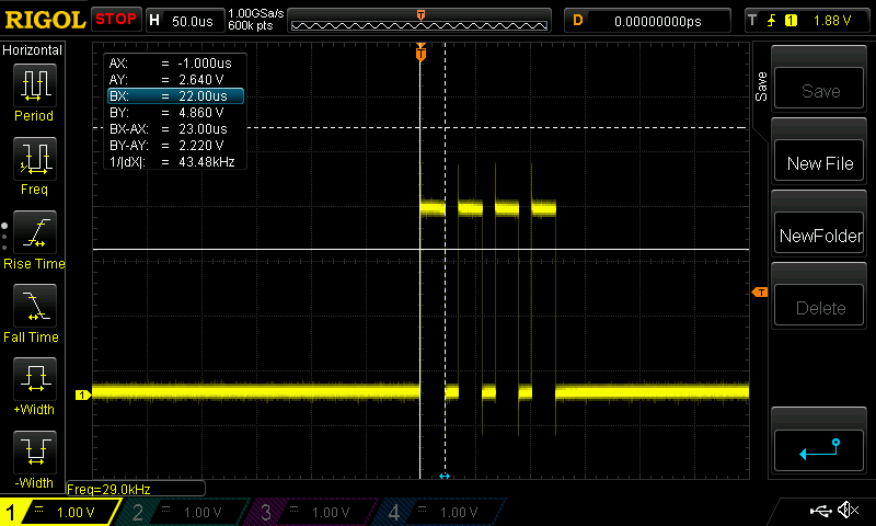
どうも4ブロック分連続して処理するようになっているらしい.理由はI2Sドライバのソースコードがないのでよくわからない(見てもわからないか…).そういうものとして理解しておこう.
次に,信号処理を限界まで追加してみる.
Lch,Rch それぞれに 512Tap の FIR + 10段のIIR Biquad を設定した. IIRフィルタの係数はL,R同じ.
コードは以下のとおり.
// I2S on ESP32-S3
// T.Uebo  October 4, 2022

// I2S Master MODE 48kHz/32bit
//
//   Mclk  GPIO 0
//   Bclk  GPIO 42
//   LRclk GPIO 2
//   Dout  GPIO 41
//   Din   GPIO 1

#include <esp_dsp.h>
#include <driver/i2s.h>
#define fsample 48000
#define BLOCK_SAMPLES 64
#define MUTE 40 // MUTE control (LOW: Mute)

//buffers
int rxbuf[BLOCK_SAMPLES*2], txbuf[BLOCK_SAMPLES*2];
float Lch_in[BLOCK_SAMPLES], Rch_in[BLOCK_SAMPLES];
float Lch_out[BLOCK_SAMPLES], Rch_out[BLOCK_SAMPLES];

// for IIR Filter
float zL0[2], zR0[2], coeffs0[5];  // Z^-1配列(Lch),Z^-1配列(Rch),係数
float zL1[2], zR1[2], coeffs1[5];
float zL2[2], zR2[2], coeffs2[5];
float zL3[2], zR3[2], coeffs3[5];
float zL4[2], zR4[2], coeffs4[5];
float zL5[2], zR5[2], coeffs5[5];
float zL6[2], zR6[2], coeffs6[5];
float zL7[2], zR7[2], coeffs7[5];
float zL8[2], zR8[2], coeffs8[5];
float zL9[2], zR9[2], coeffs9[5];

// for FIR filter
#define Nfir 512
fir_f32_t firL_st, firR_st;      //  FIRではワーク用の構造体を用意する必要がある
float coeffs_firL[Nfir], coeffs_firR[Nfir];  // 係数用配列
float z_firL[Nfir], z_firR[Nfir];  // Z^-1配列

/*-----------------------------------------------------------------------------------------------
  Setup
-------------------------------------------------------------------------------------------------*/
void setup(void) {
  Serial.begin(115200);
  delay(50);

  //Mute Control
  pinMode(MUTE, OUTPUT);
  digitalWrite(MUTE, HIGH); //unmute

  pinMode(48, OUTPUT);

  // I2S setup ------------------------------------------------------------
  i2s_config_t i2s_config = {
    .mode =  (i2s_mode_t)(I2S_MODE_MASTER | I2S_MODE_TX  | I2S_MODE_RX),
    .sample_rate = fsample,
    .bits_per_sample = (i2s_bits_per_sample_t)32,
    .channel_format = I2S_CHANNEL_FMT_RIGHT_LEFT,
    .communication_format = (i2s_comm_format_t)(I2S_COMM_FORMAT_STAND_I2S),
    .intr_alloc_flags = 0,
    .dma_buf_count = 6,
    .dma_buf_len = BLOCK_SAMPLES*4,
    .use_apll = false,
    .tx_desc_auto_clear = true,
    .fixed_mclk = 0,
  };
  i2s_driver_install( I2S_NUM_0, &i2s_config, 0, NULL);

  i2s_pin_config_t pin_config = {
        .bck_io_num = 42,
        .ws_io_num = 2,
        .data_out_num = 41,
        .data_in_num = 1
    };
  i2s_set_pin( I2S_NUM_0, &pin_config);

  //-- Filter settings -------------------------------------
  // IIR Filter の係数を生成
  dsps_biquad_gen_lpf_f32(coeffs0, 0.45f, 1.0f);
  dsps_biquad_gen_lpf_f32(coeffs1, 0.45f, 1.0f);
  dsps_biquad_gen_lpf_f32(coeffs2, 0.45f, 1.0f);
  dsps_biquad_gen_lpf_f32(coeffs3, 0.45f, 1.0f);
  dsps_biquad_gen_lpf_f32(coeffs4, 0.45f, 1.0f);
  dsps_biquad_gen_lpf_f32(coeffs5, 0.45f, 1.0f);
  dsps_biquad_gen_lpf_f32(coeffs6, 0.45f, 1.0f);
  dsps_biquad_gen_lpf_f32(coeffs7, 0.45f, 1.0f);
  dsps_biquad_gen_lpf_f32(coeffs8, 0.45f, 1.0f);
  dsps_biquad_gen_lpf_f32(coeffs9, 0.45f, 1.0f);

  //  FIR構造体の初期化
  dsps_fir_init_f32(&firL_st, coeffs_firL, z_firL, Nfir);
  dsps_fir_init_f32(&firR_st, coeffs_firR, z_firR, Nfir);

  //  FIR Filter の係数を生成.
  dsps_d_gen_f32(coeffs_firL, Nfir, 0);  // 係数列の先頭を1,その他0
  dsps_d_gen_f32(coeffs_firR, Nfir, Nfir-1); // 係数列の最後1,その他0
}

/*-----------------------------------------------------------------------------------------------
  Signal Process Loop
-------------------------------------------------------------------------------------------------*/
void loop(void) {
  size_t readsize = 0;

  //Input from I2S codec
  esp_err_t rxfb = i2s_read(I2S_NUM_0, &rxbuf[0], BLOCK_SAMPLES*2*4, &readsize, portMAX_DELAY);
  if (rxfb == ESP_OK && readsize==BLOCK_SAMPLES*2*4) {

    digitalWrite(48, HIGH);

    int j=0;
    for (int i=0; i<BLOCK_SAMPLES; i++) {
      Lch_in[i] = (float) rxbuf[j];
      Rch_in[i] = (float) rxbuf[j+1];
      j+=2;
    }

    //-------Signal process -------------------------------
    dsps_biquad_f32(Lch_in, Lch_out, BLOCK_SAMPLES, coeffs0, zL0);
    dsps_biquad_f32(Rch_in, Rch_out, BLOCK_SAMPLES, coeffs0, zR0);

    dsps_biquad_f32(Lch_out, Lch_in, BLOCK_SAMPLES, coeffs1, zL1);
    dsps_biquad_f32(Rch_out, Rch_in, BLOCK_SAMPLES, coeffs1, zR1);

    dsps_biquad_f32(Lch_in, Lch_out, BLOCK_SAMPLES, coeffs2, zL2);
    dsps_biquad_f32(Rch_in, Rch_out, BLOCK_SAMPLES, coeffs2, zR2);

    dsps_biquad_f32(Lch_out, Lch_in, BLOCK_SAMPLES, coeffs3, zL3);
    dsps_biquad_f32(Rch_out, Rch_in, BLOCK_SAMPLES, coeffs3, zR3);

    dsps_biquad_f32(Lch_in, Lch_out, BLOCK_SAMPLES, coeffs4, zL4);
    dsps_biquad_f32(Rch_in, Rch_out, BLOCK_SAMPLES, coeffs4, zR4);

    dsps_biquad_f32(Lch_out, Lch_in, BLOCK_SAMPLES, coeffs5, zL5);
    dsps_biquad_f32(Rch_out, Rch_in, BLOCK_SAMPLES, coeffs5, zR5);

    dsps_biquad_f32(Lch_in, Lch_out, BLOCK_SAMPLES, coeffs6, zL6);
    dsps_biquad_f32(Rch_in, Rch_out, BLOCK_SAMPLES, coeffs6, zR6);

    dsps_biquad_f32(Lch_out, Lch_in, BLOCK_SAMPLES, coeffs7, zL7);
    dsps_biquad_f32(Rch_out, Rch_in, BLOCK_SAMPLES, coeffs7, zR7);

    dsps_biquad_f32(Lch_in, Lch_out, BLOCK_SAMPLES, coeffs8, zL8);
    dsps_biquad_f32(Rch_in, Rch_out, BLOCK_SAMPLES, coeffs8, zR8);

    dsps_biquad_f32(Lch_out, Lch_in, BLOCK_SAMPLES, coeffs9, zL9);
    dsps_biquad_f32(Rch_out, Rch_in, BLOCK_SAMPLES, coeffs9, zR9);

    dsps_fir_f32(&firL_st, Lch_in, Lch_out, BLOCK_SAMPLES);
    dsps_fir_f32(&firR_st, Rch_in, Rch_out, BLOCK_SAMPLES);

    //------------------------------------------------------

    //Output to I2S codec
    j=0;
    for (int i=0; i<BLOCK_SAMPLES; i++) {
      txbuf[j]   = (int) Lch_out[i];
      txbuf[j+1] = (int) Rch_out[i];
      j+=2;
    }
    i2s_write( I2S_NUM_0, &txbuf[0], BLOCK_SAMPLES*2*4, &readsize, portMAX_DELAY);

  }
  digitalWrite(48, LOW);
}
これでGPIO48の信号を見てみると下のようにほぼ限界になっている.
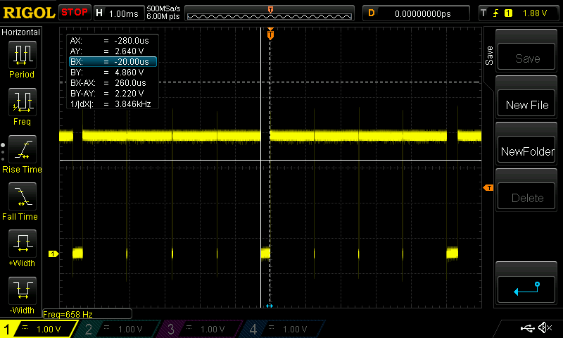
260μsの隙間があるのでもう少し詰められる.試しのFIRのタップ数を増やしていくと580くらいで出力の音がおかしくなった.
ほぼ予想どおり.
これくらいの処理能力ならデシメーション無しでSSBのベースバンド処理はいけそう.エフェクタならFIRは使わないのでかなり余裕をもって使える.
